home

Canon N3 remote release connector information
Canon makes great digital cameras, but unfortunately their marketing
department gets run of the place all too often. One such "improvement" has
been in the area of remote releases; the newer Canon digital cameras all use
the N3-style connector rather than the old-standard stereo 1/8" jack. The N3
connector is a 3-pin, snap-in that is a great solution to a non-problem,
although I'm sure it does take up a little less depth on the camera body and
certainly works fine.
As I understand it, almost all of the Canon SLR cameras have used a very
simple interface for the remote release -- there is a common pin, a focus pin,
and a shutter release pin. Connecting the focus and shutter release pins to
the common pin seems to map closely to the behavior found when you press the
shutter release button halfway or all the way down. The electrical aspect of
things is identical, regardless of whether you have a an older camera with the
stereo jack or a newer one with the N3 jack.
I heard someone describe molding their own connector with some sort of putty
or hot glue on a forum (probably dpreview.com or photo.net), and I decided to copy that approach.
It works relatively well, but I must admit that I finally needed the multiple
exposure functionality on of the nice Canon TC-80N3 and bought one.
I took some pictures of the home-made
remote release for long exposures that I built in May 2003. It works, but
it doesn't snap in as well as the Canon one because the hot glue I used is too
soft.
obtaining an N3 connector
You have three options that I know of here.
- Buy the whole remote release with an N3 from Canon
- Buy a cable from Canon with the connector on it and cut it off. Search on B&H for a Canon Remote Switch Adapter
RA-N3 for EOS 1V, 1V-HS & EOS 3 Cameras, at the time of writing they cost
$43.95.
- Purchase
- Build a connector yourself
I'm describing step #3 below.
how to make your own N3 plug out of hot glue and other stuff
Rough list of materials:
- three female pins that will fit snugly over the pins inside the N3
jack. I used pins from a PS2 mouse connector, but they weren't perfect.
- Some thin heat shrink tubing, maybe 1/16", to insulate the pins from
each other.
- some very hard-drying hot glue. I think hot glue is one of those things
that comes in 32 flavors and then some; you might check at craft stores.
Alternatively, you could make the part with some epoxy, but I wasn't certain
I could get it out of there if I did it that way. One person reports having
luck making a plug with the material used to make ear impressions for
hearing aids, and then making a mold with a two-part polystyrene resin.
- some WD-40, or equivalent lubricant to keep the glue from sticking to
the inside of the jack. Maybe PAM cooking spray would work too, or PVA if
you were using epoxy.
- masking tape. I like the blue stuff, but anything will work.
- soldering iron, solder, and a clue
Rough instructions for building the connector:
- First, solder some wires on your female pins and heat shrink some
insulation around them so that they cannot touch each other. This is
important because it's difficult to align the pins vertically inside the
small jack, but you might be able to engineer a better way of doing this.
- Make sure you're comfortable spraying WD-40 or another lubricant inside
the N3 jack on your camera. I was, but then again I'm pretty tough on some
of my gear.
- Make a mask of some sort to protect most of the camera from the spray of
the WD-40 (or whatever anti-stick stuff you want to use). Masking tape with
a small hole cut in it to expose the jack is what I used, and I covered the
rest of the camera with a piece of paper to protect it from overspray.
Spray a light burst of WD-40 in to the jack to keep the glue from
sticking. There are probably better approaches, and this may not even be
necessary for some hot glues.
- Now, plug them on to the pins inside the jack. The order is not
critical, as you haven't wired anything yet, but you might as well do it in
some reasonable way. Fold the wires over as they come out of the jack so
that your wires will hang down when the camera is oriented normally.
- Have a trusted assistant dump some hot glue in to the jack while you
pray that they don't touch your fingers with the tip of the glue gun or the
glue. Make sure that you get enough glue down there to really fill it, or
else your connector will have trouble registering.
- Once the glue cools, try removing the connector. It should pop right
out. If not, you could easily scrape it all out with a dental pick without
any damage to the camera.
Wiring things up
As I said before, there isn't any real magic to the electrical operation of
the remote releases. As long as you don't apply any external voltages to the
pins on the camera I do not see how you could damage it, but your milage may
vary :)
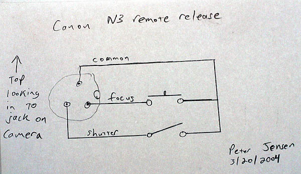
On my personal Canon D60 camera, I have experimentally found the pins to be
such: View the camera from the side, with the top of the camera up. The pins
are in a triangle, and the top one is the common. The lower left is the
shutter release, and the lower right is the focus. I found this out by
sticking my pocket knife in there and shorting pins until the camera either
focused or took pictures. Do note that the schematic below shows the pins
looking in to the jack on the camera; the little bump on the right is what
keeps you from plugging things in backwards.
other useful links
Have questions?
This all works for me, but if you have any questions or suggestions I'd be
happy to update this information. Alternatively, start a thread on one of the
linkable online photography communities and I'll link to it here.
-Peter Jensen, a random photographer.